|
|


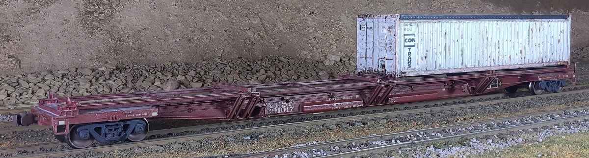


ATSF 291017 Ft-65 COFC conversion
When Santa Fe needed more container-on-flat-car (COFC) platforms to handle
growing intermodal traffic, railroad shop forces met the challenge by converting
outdated Ft-65 class Flexi-Van flat cars into light-weight flat cars specialized for
container loading. Santa Fe removed the Flexi-Van trailer equipment and
installed a complex framework to carry 20' or 40' containers, keeping the Ft-65
class designation. Most, if not all, were painted brown with white markings.
I made my Ft-65 model by modifying a Walthers Flexi-Van car, adding brake
rigging details and scratch-building the COFC frame from styrene shapes and
sheet stock. Decals came from an assortment of Microscale sets.
A big thanks to the photographers who shared their Ft-65 photos online!
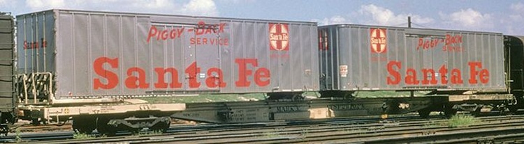
Right: A Santa Fe Ft-65 Flexi-Van
flat car before modifications to a
COFC platform. Note the trailer
handling equipment on top the
end platforms and the centersill.
Also note the unusual Rockwell
trucks - some cars kept these
trucks after the modifications.
flat car before modifications to a
COFC platform. Note the trailer
handling equipment on top the
end platforms and the centersill.
Also note the unusual Rockwell
trucks - some cars kept these
trucks after the modifications.
-- About
-- Contact
-- Diesels
-- Links
entire website copyright Gregg Fuhriman
created with CoffeeCup Visual Site Designer
created with CoffeeCup Visual Site Designer
-- Layouts
-- Modules
-- Signalling
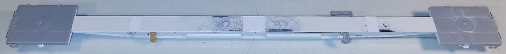
I started with a Walthers Mark III Flexi-Van car. One major regret: only after completing the build did I stumble upon the fact that Walthers also
made a Mark IV model, which is a more accurate starting point for the Ft-65 class. Since I'd already invested many hours in building the COFC
rack and the detailed brake rigging, I said "good enough" and moved on.
To begin, I removed the trailer handling gear and brake parts, some of which I re-used.
I stripped the white paint from the plastic end platforms, and the lettering from the centersill.
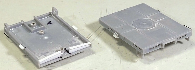
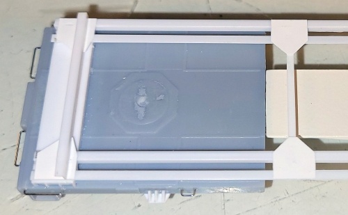
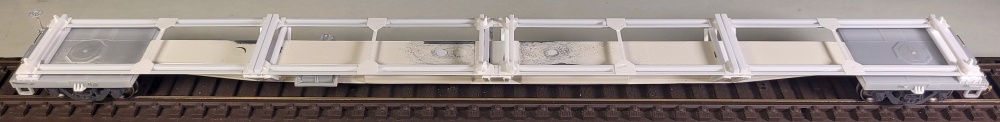
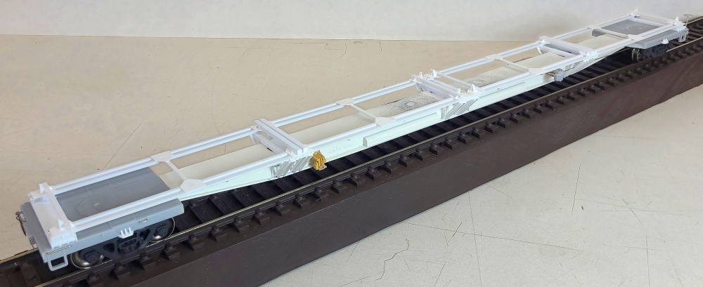
Below: After brake rigging, the next task was making the container rack, built in-place from the bottom up. I started by filling the
big holes on top the centersill (from the removed Flexi-Van equipment), and generally smoothing out casting imperfections. I
ACC-glued 0.005" styrene panels where the rack's cross-members will attach to the centersill. These allow for styrene-to-styrene
bonds, which are sturdier than if I'd just ACC-glued the cross-members directly to the metal centersill.
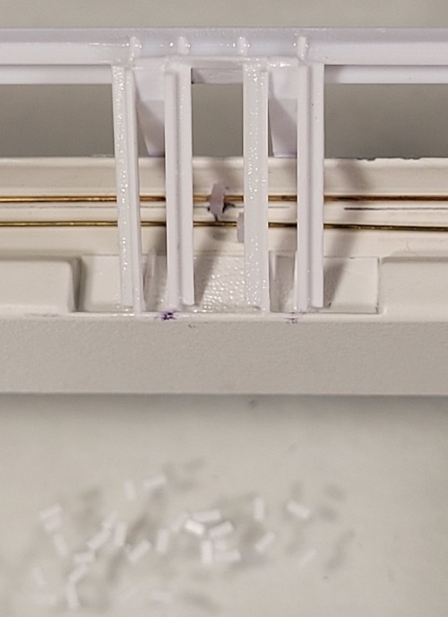
Above: At each group of angled supports, the longitudinal
members have four reinforcing ribs, which I made from tiny
bits of 0.010" styrene.
Left: At the ends, the longitudinal members have
three reinforcing ribs both inside and outside.
members have four reinforcing ribs, which I made from tiny
bits of 0.010" styrene.
Left: At the ends, the longitudinal members have
three reinforcing ribs both inside and outside.
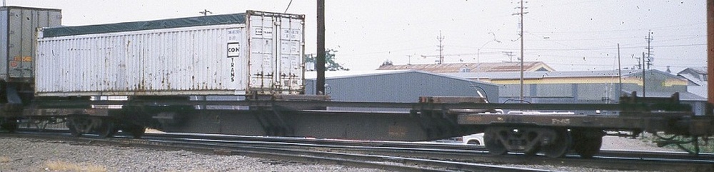
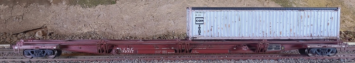
Below: The inspiration for my model is my photo of this modified Ft-65 passing through Stockton CA in April 1988. It's so dirty,
I have no idea what car number it is - only the "Ft-65" marking is legible. I also replicated the ConTrans open-top 40' container.
I have no idea what car number it is - only the "Ft-65" marking is legible. I also replicated the ConTrans open-top 40' container.
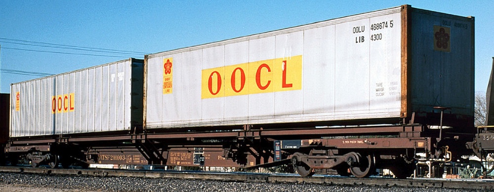
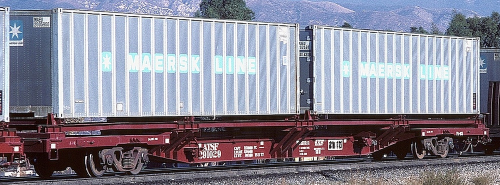
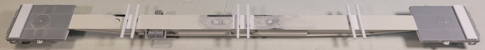
Below: Ft-65 291029 soon after its modification into a COFC platform, based on how clean it is. These cars
seemed to have no set standardized lettering/marking arrangement - compare to cars 291003 and 291004, below.
seemed to have no set standardized lettering/marking arrangement - compare to cars 291003 and 291004, below.
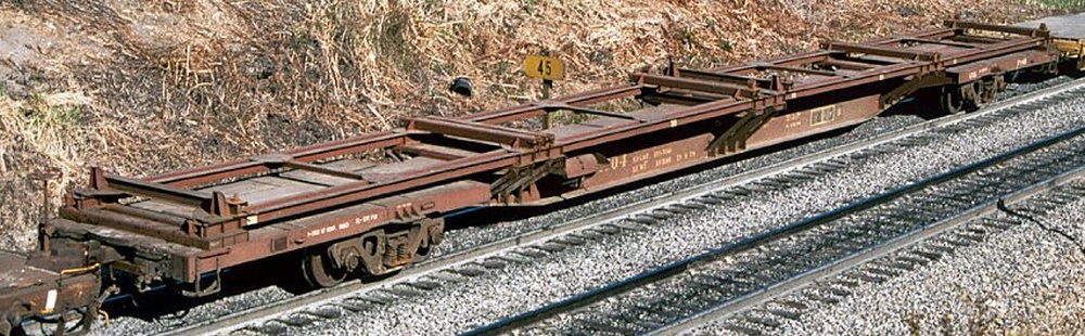
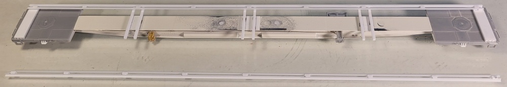
Below: This project wouldn't have been possible without this down-on photo - another big thanks to
the photographer who shared it online! This is Ft-65 291004, with standard trucks. I also based my
weathering efforts on this photo, as it's not freshly-painted clean, but the markings are still visible.
the photographer who shared it online! This is Ft-65 291004, with standard trucks. I also based my
weathering efforts on this photo, as it's not freshly-painted clean, but the markings are still visible.
Below: Ft-65 291003 kept its Rockwell trucks through the modification process.
I would have liked to put Rockwells on my car, but could not find a model of this truck.
I would have liked to put Rockwells on my car, but could not find a model of this truck.
Below: I've tried to replicate the weathering seen on prototype car 291004 (above). But even after two rounds of
PanPastels 780.5 Raw Umber powder and dull coting, the road dust is barely visible. I also did a wash of light gray
artist's oil paint, very diluted with mineral spirits. This is visible on the top surfaces, as seen on car 291004 (above).
PanPastels 780.5 Raw Umber powder and dull coting, the road dust is barely visible. I also did a wash of light gray
artist's oil paint, very diluted with mineral spirits. This is visible on the top surfaces, as seen on car 291004 (above).
Right: I used styrene
channel to make
angled supports at
the platform inside
edges for a more
finished look.
channel to make
angled supports at
the platform inside
edges for a more
finished look.
Right: I used 0.010"
styrene to make the
bolster gussets found
on each side of the
platforms.
styrene to make the
bolster gussets found
on each side of the
platforms.
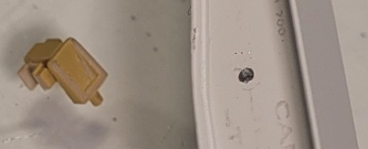
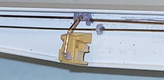
Right: On the left side
toward the A end is a
small brake item (not
sure what it is).
I fudged it by
reshaping a triple
valve from another kit,
and drilled a mounting
hole in the centersill.
I added wire piping
to connect this part
into the train line.
The pipe supports
and junctions are
custom 3D printed
parts.
toward the A end is a
small brake item (not
sure what it is).
I fudged it by
reshaping a triple
valve from another kit,
and drilled a mounting
hole in the centersill.
I added wire piping
to connect this part
into the train line.
The pipe supports
and junctions are
custom 3D printed
parts.
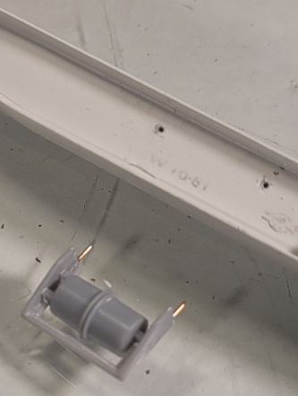
Right: I re-used the
Flexi-Van air reservoir,
but added wire
mounting pins for
added strength.
but added wire
mounting pins for
added strength.
Right: The completed
platforms including
the wire grabs that
came with the car.
platforms including
the wire grabs that
came with the car.
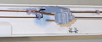
Right: The A end left-side air piping.
Right: The B end left-side air piping.
Right: I re-used the
Flexi-Van triple valve,
with added holes for
its wire piping.
with added holes for
its wire piping.
Below: The completed brake rigging on the left side.
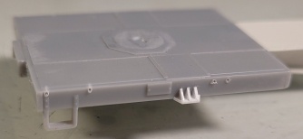
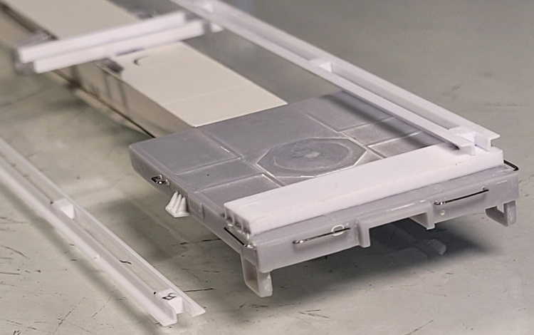
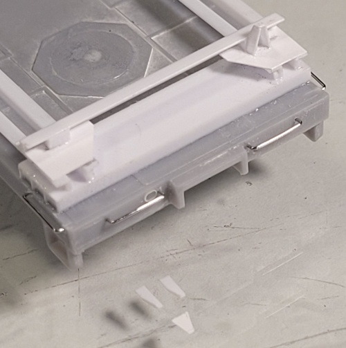
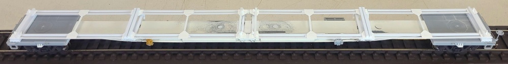
Below: The cross-members are 0.060" thick styrene, cut to a width matching a container body width. The two end members
are 0.312" wide channels, flange side down, with fillers inset into each end. The six mids are 0.060" square strip. These are
spaced to support the ends of four 20' containers, with a gap at the center of the car (see the prototype photos, above).
are 0.312" wide channels, flange side down, with fillers inset into each end. The six mids are 0.060" square strip. These are
spaced to support the ends of four 20' containers, with a gap at the center of the car (see the prototype photos, above).
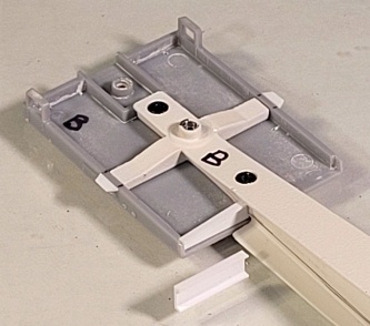
Below: The longitudinal members are each made of two 0.060" angles, with small 0.060" spacer blocks that align
with the cross-members. Additional spacer blocks are located midway at each of the four 20' container positions.
with the cross-members. Additional spacer blocks are located midway at each of the four 20' container positions.
Right: The longitudinal members
with spacer blocks are placed
so that their outside edges match
the width of a container (slightly
wider than the Flexi-Van platforms).
In the insets of the end cross members, I used tiny bits of 0.010" styrene to model the four
reinforcing ribs.
with spacer blocks are placed
so that their outside edges match
the width of a container (slightly
wider than the Flexi-Van platforms).
In the insets of the end cross members, I used tiny bits of 0.010" styrene to model the four
reinforcing ribs.
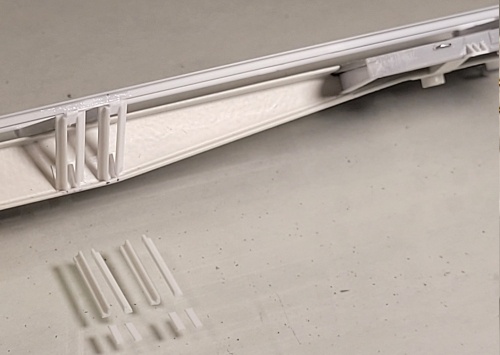
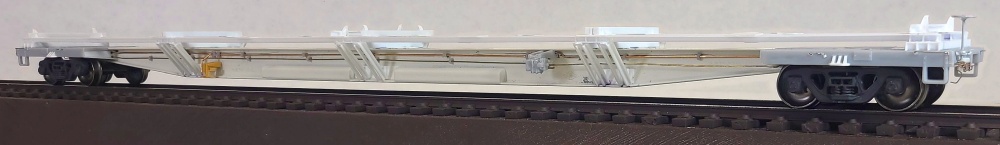
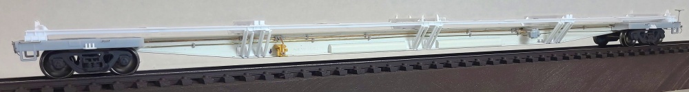
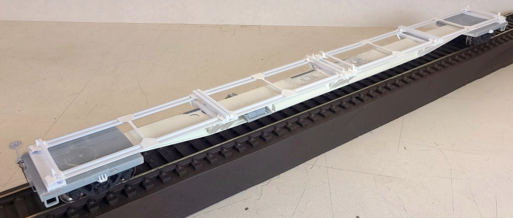
Right and Below: Each side had three groups of four angled supports
that connect from the centersill's bottom flange up to the rack's
longitudinal members. I made these from 0.047" (3/64") angle strip.
At their tops, they are attached to the 0.060" square cross-members.
At their bottoms, I ACC-glued 0.005" styrene panels to the centersill,
then glued on 0.010" vertical flanges, to which the angled supports
are glued.
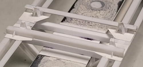
Below: Next, on top the longitudinal members I installed gusset plates
made from 0.010" styrene. Also, at the midpoints of each 20' container
position, I added 0.063" (1/16") T-shaped cross-members, each of
which also has gusset plates (right).
made from 0.010" styrene. Also, at the midpoints of each 20' container
position, I added 0.063" (1/16") T-shaped cross-members, each of
which also has gusset plates (right).
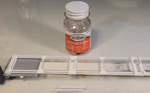
Below: The gusset plates have various shapes depending on their
position along the car - I tried to replicate what I could see in the
top-down prototype photo. I used Testors styrene cement for this build.
position along the car - I tried to replicate what I could see in the
top-down prototype photo. I used Testors styrene cement for this build.
Left and Below: On top the gussets are the container cross-supports,
made from 0.060" angle mounted cross-wise. These have added
styrene blocks, placed in alignment with the innermost longitudinal
members, to add support for these angle strips mounted on-edge.
There is one cross-support at each end of each 20' container position,
for a total of eight.
The blocks also help support the container guides, made of two bits
of vertical styrene forming an upside-down "V" shape. The rub
surface of these are made from 0.005" styrene bits in a trapezoid
shape and "folded" a bit to follow the profile of the vertical bits.
Finally, tiny triangle-shaped reinforcements made of 0.010" styrene are
added to each container cross-support and its corresponding gussets.
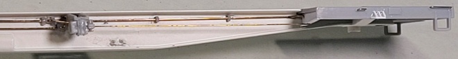
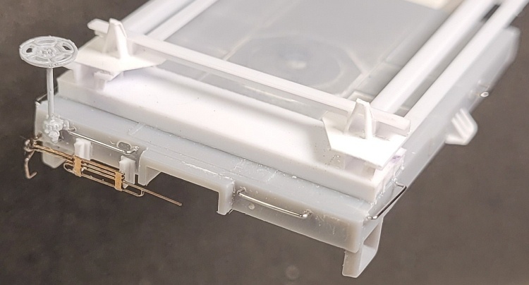
Right: The finished B end.
The container supports and
guides are visible here.
The vertical brake wheel is a part
found in my scrap box, which I felt
is more accurate than the stock
Flexi-Van part.
For the cut lever, I modified a
Plano Models #12002 etched
metal part and mounted it to
two small bits of styrene T strip.
The container supports and
guides are visible here.
The vertical brake wheel is a part
found in my scrap box, which I felt
is more accurate than the stock
Flexi-Van part.
For the cut lever, I modified a
Plano Models #12002 etched
metal part and mounted it to
two small bits of styrene T strip.
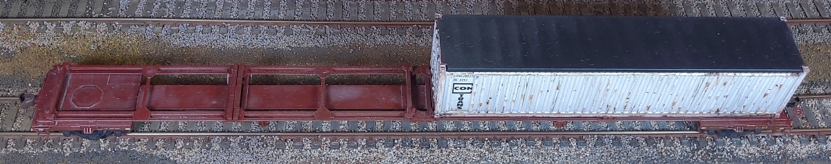
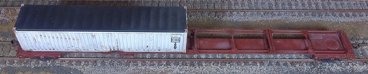
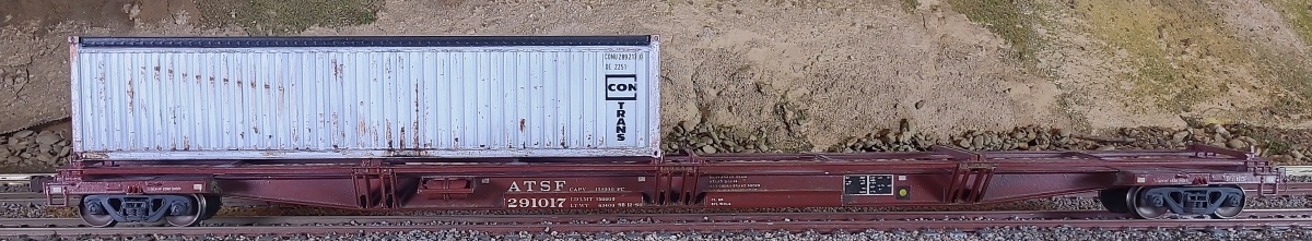
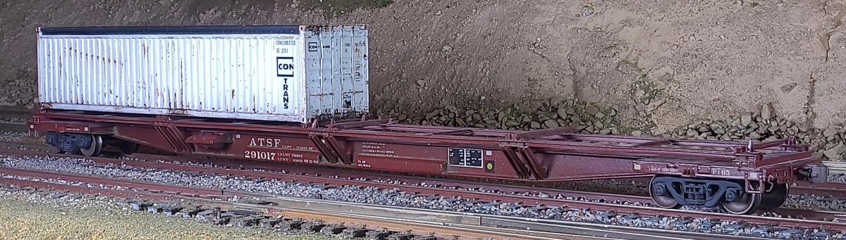
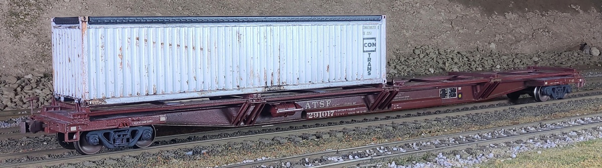
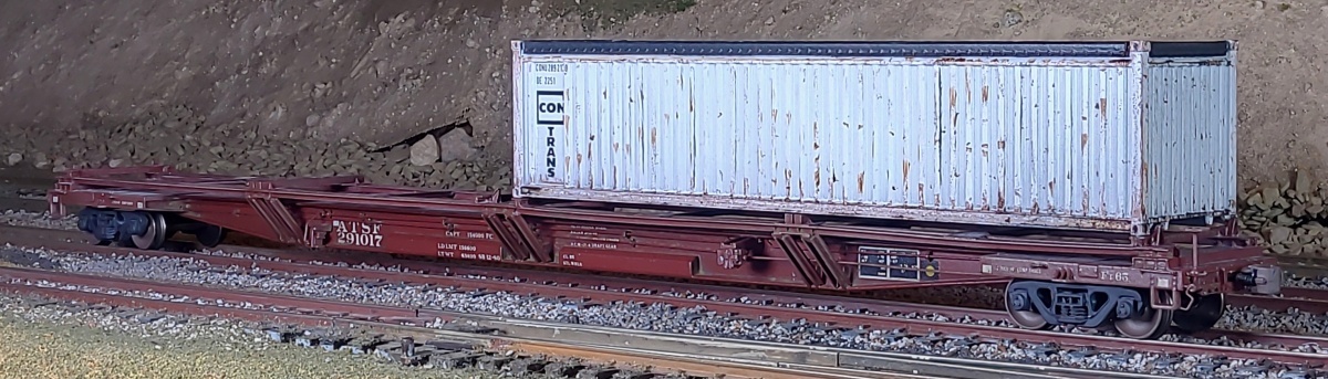
Below: Here are several views of the completed build. I finished the car with a coat
of ATSF Mineral Brown, and decals gathered from several Microscale sets.
of ATSF Mineral Brown, and decals gathered from several Microscale sets.