|
|

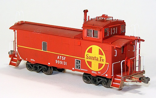
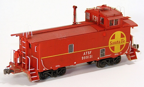
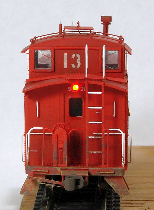

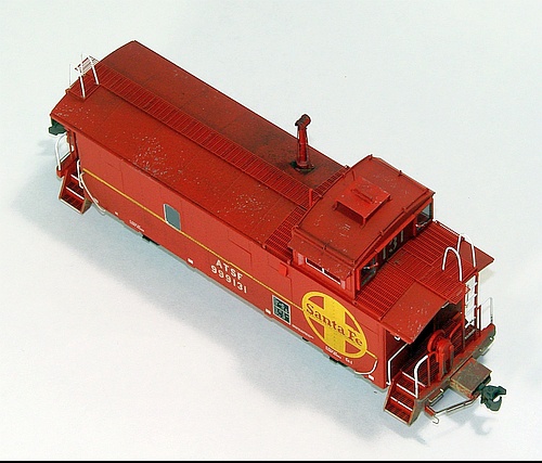
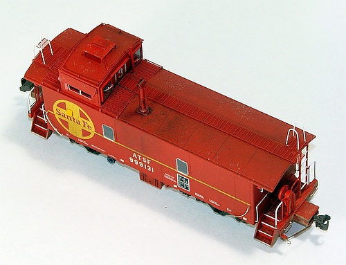

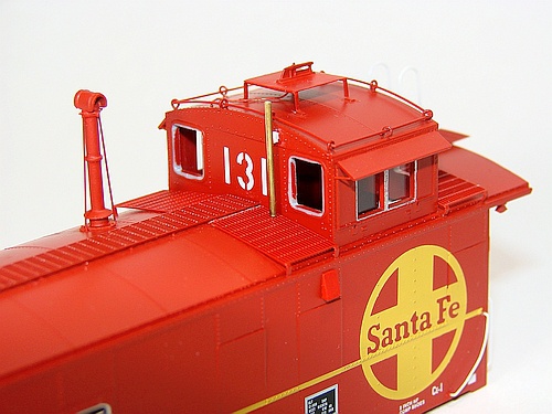
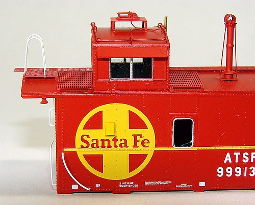
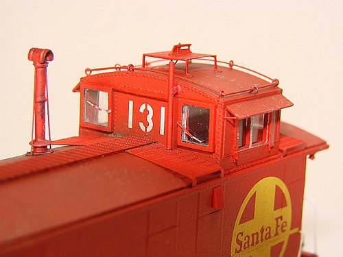
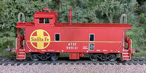


ATSF Ce-1 Waycar 999131
Centralia Car Shops makes a terrific Santa Fe waycar, but there are several ways to improve it.
Starting from a pre-decorated ready-to-run model, I installed red LED end warning lights and
a basic DCC decoder to control them. I also replaced and added several details, along with
weathering to create a more accurate and realistic model. An indispensible resource for this
project was the all-color book "Santa Fe Waycars" by Stephen Priest (out of print).
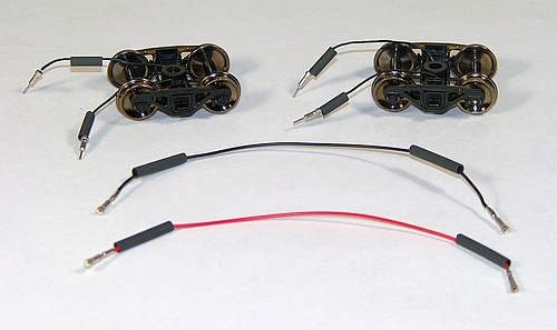
I replaced the stock trucks with Athearn 4593 modern caboose trucks.
These have power pickups, to which I soldered small pins in case
I ever need to remove the trucks. I built two wires with mating
receptacles for connection to the DCC decoder inside the car.
These have power pickups, to which I soldered small pins in case
I ever need to remove the trucks. I built two wires with mating
receptacles for connection to the DCC decoder inside the car.
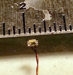
I hand-soldered tiny transformer
wire to Surface-mount style red
LEDs (0603 size). The ruler
reveals the minute scale of this
solder work.
reveals the minute scale of this
solder work.
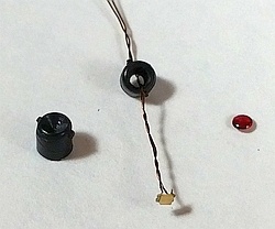
I shortened Detail Associates
1014 "Canadian Back-up Light"
parts (left) and drilled them out
(center) to house the tiny red
LEDs. The transformer wire has
an insulated coating, allowing it
to be twisted without electrical
shorts. Red MV Lenses (right)
were added after painting.
1014 "Canadian Back-up Light"
parts (left) and drilled them out
(center) to house the tiny red
LEDs. The transformer wire has
an insulated coating, allowing it
to be twisted without electrical
shorts. Red MV Lenses (right)
were added after painting.
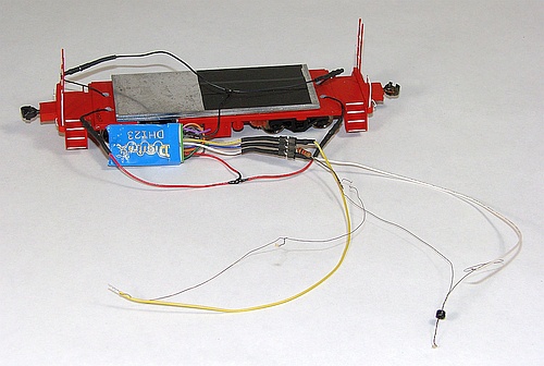
I've temporarily connected the wiring for testing.
The Digitrax DH123 decoder's functions are
used to control the red lights with DCC.
The Digitrax DH123 decoder's functions are
used to control the red lights with DCC.
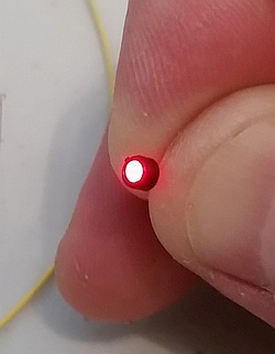
It works! A red LED
mounted in its housing and
lit up under DCC control.
mounted in its housing and
lit up under DCC control.
The housings and all other added details were brush-painted
red before installation. I drilled small holes through the end
walls for routing the transformer wires into the body. When the
waycar is viewed from above or the side, these holes are
hidden below the end roof eaves.
red before installation. I drilled small holes through the end
walls for routing the transformer wires into the body. When the
waycar is viewed from above or the side, these holes are
hidden below the end roof eaves.
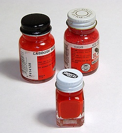
For painting added details,
I blended a custom mix of
90% Polly-S Caboose Red
and 10% Polly-S ATSF Red
in an old Testors bottle.
I blended a custom mix of
90% Polly-S Caboose Red
and 10% Polly-S ATSF Red
in an old Testors bottle.
Completed light installation, using ACC adhesive.
Separating the car body from the floor took a bit of experimentation, but once solved it's not difficult to do (unfortunately, I didn't
take photos of this process). First, carefully pry loose the tops of the ladders from the end roof eaves - there is a weak glue joint
there. The ladders are pliable and can take some amount of bending. Next, from the bottom side, carefully wedge a flat-tip #17
Xacto blade into the seam between the sides of the body and the car floor. Work this along the sides until you're certain the seam
is loose (on my model, this seam appeared to be loose right out of the box). Finally, carefully fit the #17 blade between the end
ladder and brake stand, wedge it into the seam between the platform and the end wall, and gently twist the blade to break the
glue joint and lift the body up away from the platform. Do this at both ends, and the body should now be loose from the floor.
Left: A view of the plug/receptacle connections for the trucks. I drilled
holes through the floor, large enough for the connectors to pass
through in case the trucks ever need to be removed.
I modified the Athearn truck mounting ring, and the Centralia bolster
system, to ensure the couplers sit at the correct height. I used the
stock couplers - they're permanently installed in the centersill and
I didn't want to risk damaging it.
Note: the Athearn 4593 trucks come with an axle generator on one
truck, but it's on the wrong (outer) axle and it's partly molded into the
truck sideframe! To solve this, I bought two pairs of trucks and used
the two non-generator trucks (the two generator trucks can be used
for a future project).
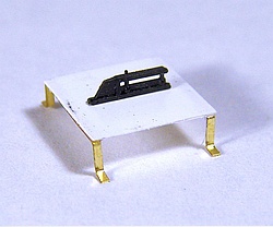
I installed a brass generator from American Scale Models on the
inner axle at the cupola end. However, it stands up quite high and
interfered with the car floor. I cut out an area of the floor (the white
plastic visible here) to clear the generator. This was later painted
black to disguise it.
Below: The completed axle generator sits up into the
carbody per the prototype. Also, I painted the sealed
window frames aluminum to match the prototype.
holes through the floor, large enough for the connectors to pass
through in case the trucks ever need to be removed.
I modified the Athearn truck mounting ring, and the Centralia bolster
system, to ensure the couplers sit at the correct height. I used the
stock couplers - they're permanently installed in the centersill and
I didn't want to risk damaging it.
Note: the Athearn 4593 trucks come with an axle generator on one
truck, but it's on the wrong (outer) axle and it's partly molded into the
truck sideframe! To solve this, I bought two pairs of trucks and used
the two non-generator trucks (the two generator trucks can be used
for a future project).
I installed a brass generator from American Scale Models on the
inner axle at the cupola end. However, it stands up quite high and
interfered with the car floor. I cut out an area of the floor (the white
plastic visible here) to clear the generator. This was later painted
black to disguise it.
Below: The completed axle generator sits up into the
carbody per the prototype. Also, I painted the sealed
window frames aluminum to match the prototype.
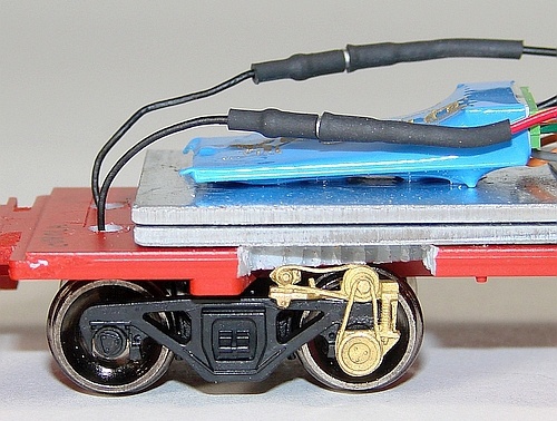
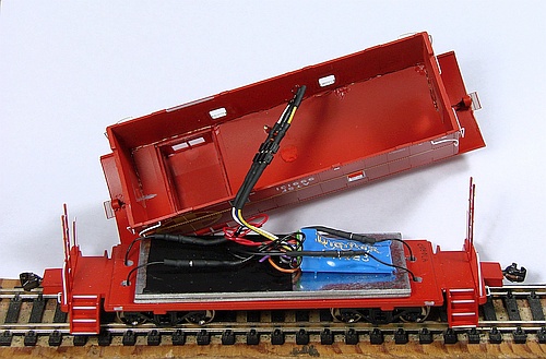
Below: The complete wiring installation. I tack-glued the
transformer wires from the end lights into the upper
corners of the body and soldered on short lengths of
standard wire with connector pins. These are plugged
into receptacles soldered to the decoder's wiring harness,
allowing the car body to be "unplugged" from the floor.
transformer wires from the end lights into the upper
corners of the body and soldered on short lengths of
standard wire with connector pins. These are plugged
into receptacles soldered to the decoder's wiring harness,
allowing the car body to be "unplugged" from the floor.
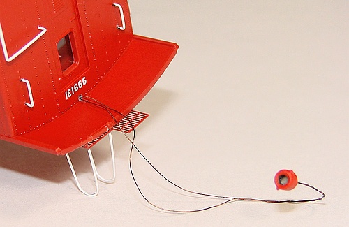
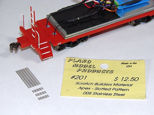
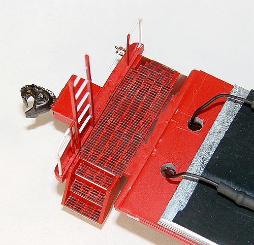
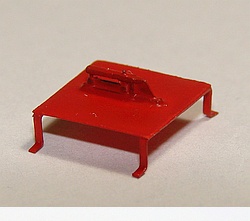
Below: To simulate treadway grating on the end platforms and
steps, I cut pieces to size from a sheet of Plano Models
201 Apex Slotted-Pattern stainless steel material, and painted
them red before installation. I painted the stock platforms flat black
before ACC gluing on the gratings. Some of the red paint chipped
off, which gives these a prototypical worn look. This method is an
acceptable compromise to a full "see-through look". I chose to not
open the platforms and steps as I was concerned about
compromising mechanical integrity of the platforms.
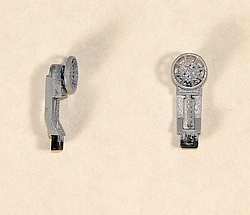
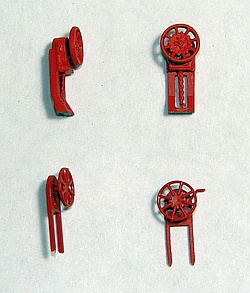
I replaced the stock brake stands and wheels with parts
from an Athearn "blue box" caboose. Compare the "beefier"
Athearn parts (top) to the undersized Centralia parts (bottom).
from an Athearn "blue box" caboose. Compare the "beefier"
Athearn parts (top) to the undersized Centralia parts (bottom).
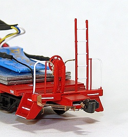
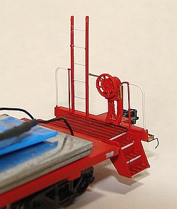
Plano coupler cut bars were modified for the ends.
Bits of brass wire were shaped to complete the railings.
Bits of brass wire were shaped to complete the railings.
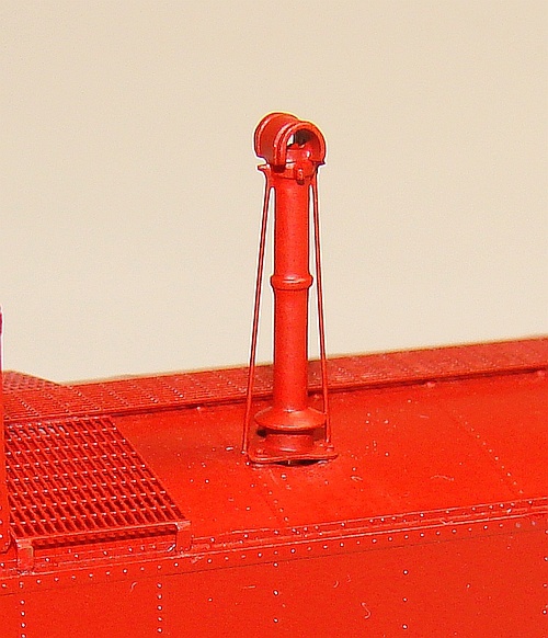
Below: a brass smoke jack from American Scale Models, shortened
below the top cap, replaced the stock part. Wire supports were added.
below the top cap, replaced the stock part. Wire supports were added.
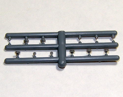
Below: Cannon & Co. 2052 step lights were assembled on the sprue.
Right: I installed these at the corners of the caboose and then painted
them red. Also, this is a good photo of the yellow-painted sloped vent
added above the "n" and "t" in the yellow herald (discussed below).
Right: I installed these at the corners of the caboose and then painted
them red. Also, this is a good photo of the yellow-painted sloped vent
added above the "n" and "t" in the yellow herald (discussed below).
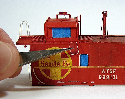
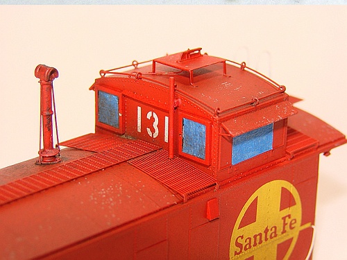
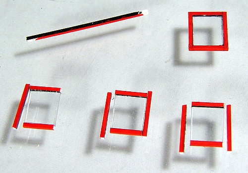
The Centralia model has sealed windows on the front and rear of the cupola - this is incorrect for Ce-1 waycars. I replicated the "box frame"
look of these windows using small styrene strip painted black on the inner surface and red on the adjacent and opposite surfaces. The fourth
surface was left bare for gluing to the cupola. 0.015" thick clear styrene was cut to size and "framed" with the painted styrene strip using
clear canopy glue. On the cupola, the sealed window frames were sanded smooth and the rounded corners cut away in preparation for
attaching the new windows. Once installed, the "glass" was temporarily covered with painters tape during the weathering process.
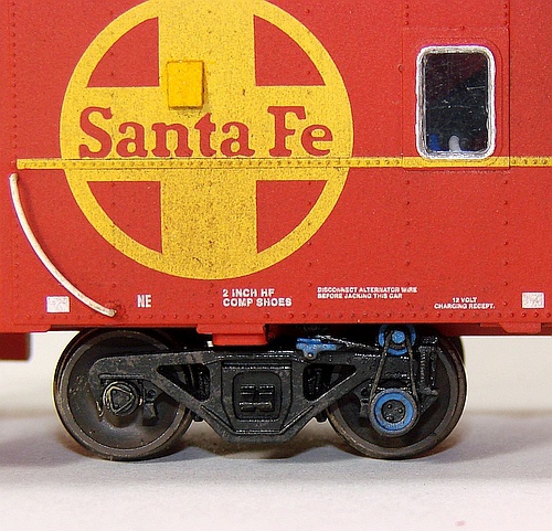
The Centralia model is missing the sloped vents found on both
sides of Ce-1 waycars. Left: a red-painted vent is visible above and
left of the yellow herald. A yellow-painted vent was installed on the
opposite side in the yellow herald above the "n" and "t". I shaped
these vents from 0.040" thick styrene and brush painted. A small
patch of the stock paint was scraped away to expose the body
plastic, where the new vents were attached with styrene cement.
Right: On my model, the stock window "glass" had come loose from
the side windows. I discarded those and replaced them with 0.015"
clear styrene cut to match the sealed window shape. These are
attached with clear canopy cement, resulting in flush-mounted
"glass" that is more prototypical.
Final assembly: The body-mounted light plugs were connected to
the floor-mounted receptacles and a final DCC test of the red end
lights performed. To mate the body to the floor, the end ladders
were gently held clear of the roof eaves as the body was pressed
back down onto the floor. I chose not to glue the body in place, as it
holds quite well with friction alone and I want to have easy access
to the interior in case the electronics need servicing in the future.
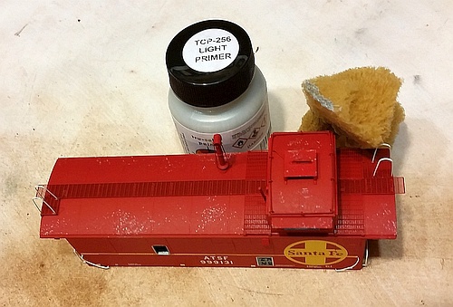
Left: To simulate flaking red paint on the roof exposing underlying
metal (a common sight on ATSF waycars), a sea sponge from the
art supply store was used to gently "dry-dab" on primer gray paint
resulting in tiny specs.
Next, roof brown paint was dry-brushed on the end surfaces of steps
and sills, along with the battery box ends and also the trucks. This
was followed by dry-brushed dust colored paint to simulate the
typical road grime that accumulates around these low areas (see
the finished images at top of page).
Dry powder chalks were applied over the roof and sides, fixed in
place with Testors Dullcote spray. Wheels and couplers were
brush-painted roof brown.
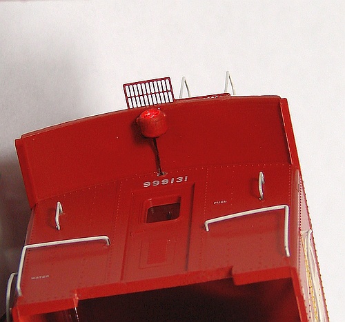
Below: The antenna is a Detail Associates 1803 Sinclair type on a
scratch-built platform using brass strip and styrene sheet. Brass wire
simulates the antenna electrical cable. Also, a brass wire vent pipe
was added adjacent to the cupola.
scratch-built platform using brass strip and styrene sheet. Brass wire
simulates the antenna electrical cable. Also, a brass wire vent pipe
was added adjacent to the cupola.
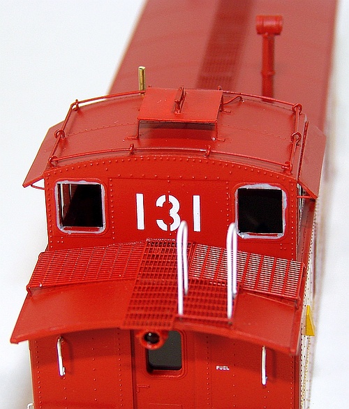
Right: I added wire sunshade supports per the prototype. After
weathering, A-Line 29202 short window wipers were installed
on the cupola end window frames. Details Associates 2312 straight
cab air deflectors, their inner edges painted red, were installed
adjacent to the cupola side windows using clear canopy glue.
weathering, A-Line 29202 short window wipers were installed
on the cupola end window frames. Details Associates 2312 straight
cab air deflectors, their inner edges painted red, were installed
adjacent to the cupola side windows using clear canopy glue.
-- About
-- Contact
-- Diesels
-- Links
Right: ATSF 999139 is typical of
the Ce-1 waycar class I modeled.
the Ce-1 waycar class I modeled.
entire website copyright Gregg Fuhriman
created with CoffeeCup Visual Site Designer
created with CoffeeCup Visual Site Designer
-- Layouts
-- Modules
-- Signalling