|
|


Mojave Free-mo Module - Control Panels
Mojave is a yard module built to the Free-mo modular railroad standard, and was constructed circa 2007 as a
group effort by the Northern California Free-mo group I helped found. In Free-mo, yards and return loops
are crucial, acting as train origination and destination "end points" on the single- or double-track railroad.
I did the design work using MS Visio, installed the scenery, and built the control panels as described here.
Gary Green did the frame construction and track installation, and other members contributed to the wiring work.
Mojave and its control panels have proven to be quite reliable over the years, and I attribute this
to the detailed, thorough up-front planning and robust construction materials and methods used.
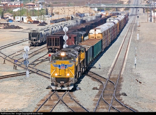
Above: The real Mojave yard, located at the eastern end of
California's Tehachapi Pass, acts as a real-life staging yard for
trains moving over the busy line. The yard is long, straight, and
narrow, which was the inspiration for naming this module "Mojave".
California's Tehachapi Pass, acts as a real-life staging yard for
trains moving over the busy line. The yard is long, straight, and
narrow, which was the inspiration for naming this module "Mojave".
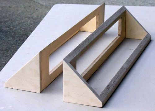
Below: I designed the panel frames in MS Visio, and
Gary Green built them from high-quality Baltic Birch plywood.
Gary Green built them from high-quality Baltic Birch plywood.
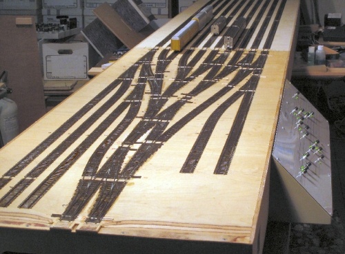
Above: Our Mojave yard before scenery. The track plan does not
replicate the real Mojave - rather, it is designed specifically to
optimize train movements on Free-mo layouts. Usually, a two-track
module is mated to Mojave to create a switching lead parallel to the
main line. The two parallel tracks allow an incoming train to arrive
via the right lead onto one of the four right-most tracks, while in
parallel a switcher uses the left lead to work the seven left-most tracks.
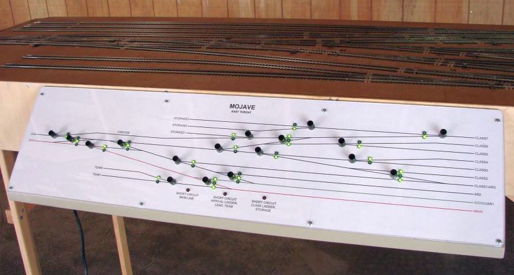
Above: A finished control panel mounted to the Mojave module. I built two panels (one for each side) that are mirror images so the
panel's track diagrams match the operator's viewpoint of the physical track. This is the "north" panel, since it mounts to the "north" side
of the module. Each Tortoise-powered track turnout has a corresponding pushbutton (black buttons) on each panel, except for
cross-overs which have a single button controlling two turnouts in tandem. The green LEDs indicate which route is selected. Free-mo
operators have learned to "follow the lights" on the panels, as opposed to examining the turnout points, for setting the desired route.
Along the bottom of each panel are three red LEDs - these illuminate should a power overload occur on the corresponding power
district. Mojave is divided into three power districts, each protected by a dedicated overload breaker. This way, only a portion of the yard
shuts down when a short-circuit happens (for example, an operator's locomotive inadvertently splits a switch, or a derailment occurs).
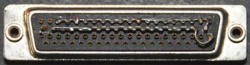
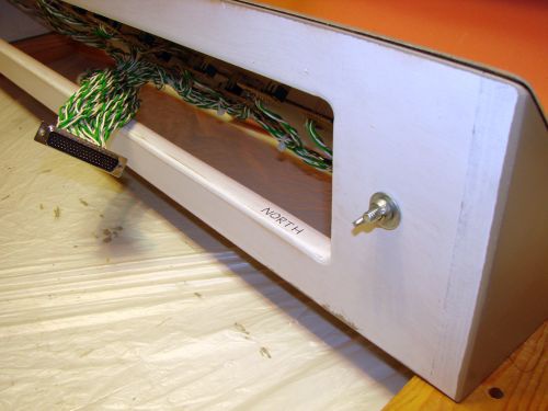
Left: The panels have 1/4 inch hardware for
bolting to the module sides. 78-pin D-sub
connectors thread through openings in the
module side and plug into the module underside.
bolting to the module sides. 78-pin D-sub
connectors thread through openings in the
module side and plug into the module underside.
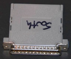
Right: The panel wiring is
designed to allow using only
one panel, either the "north"
panel by itself or the "south"
panel by itself. This feature
allows placing Mojave flush
against a wall in a layout room,
thereby optimizing the setup
space. In this case, the
module-side connection for
the unused panel is "bypassed"
by plugging in a special connector "dongle" - here is the
"south" panel bypass dongle.
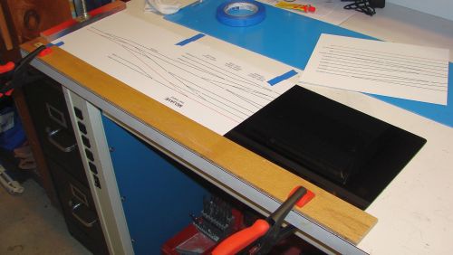
Below: I designed the panel diagram artwork in MS Visio and
printed it on high-quality paper. The panels are exactly 33 inches
long, and the diagrams are printed across three 8.5x11 inch sheets
of paper set end-to-end. These were glued onto a Masonite
hardboard backing as shown here. The diagrams are protected
by clear Plexiglas overlays. The Plexiglas and hardboard (with
diagrams) were sandwiched together for drilling out all the holes
for pushbuttons and LEDs (thanks to Jesus Pena and his nice drill
press setup!). Special drill bits were required for drilling the
Plexiglas to prevent chipping and cracking.
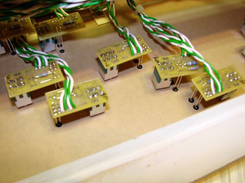
Below: To simplify the wiring work, I designed a custom circuit
board that holds a pushbutton, the route-indication LEDs, and their
current-limiting resistors. The board is designed for use on either a
single turnout (one pushbutton and two LEDs) or a cross-over (one
pushbutton and three LEDs). The boards are held in place using the
washer-and-nut hardware that comes with the pushbutton. The
long-leaded LEDs stand up high and fit into mounting clips (black).
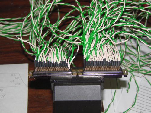
Below: The wiring from all the pushbutton boards comes together
at the 78-pin D-sub connectors. The two panels are wired in series:
12-volt DC power sourced from a power supply in the module routes
into one panel, fans out in parallel to all the pushbuttons, then back
out to the module and over to the second panel. The parallel wiring
continues through all of its pushbuttons, then back out to the module
where it connects to the individual Tortoise motors. This is then
routed back into the panels for illuminating the LEDs indicating
the actual Tortoise positions.
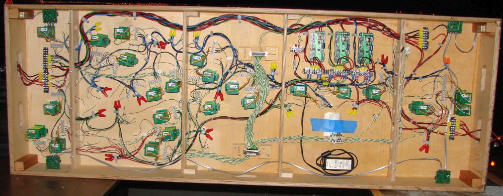
Below: The underside of the Mojave throat section. At center, a bundle of green and white
wires connects the two 78-pin D-sub connectors to which the panels connect. The upper
connector (south panel) receives the 12-volt DC power from the power supply. The lower
connector (north panel) has additional green/white wires fanning out to the Tortoise machines.
Note: If you ever get the bug to build a yard with powered turnouts, first stare at this picture
for a while. You might change your mind. Or you might be totally inspired! Either way,
it's always good to have a clear idea of what is involved before jumping in.
-- About
-- Contact
-- Diesels
-- Links
entire website copyright Gregg Fuhriman
created with CoffeeCup Visual Site Designer
created with CoffeeCup Visual Site Designer
-- Layouts
-- Modules
-- Signalling