|
|


ATSF 298993 Ft-93 10-pack Fuel Foiler Spine Car
CONSTRUCTION
Starting from Athearn's "Impack" spine car kits (2 end units and 8 mid units), I replaced the
trailer platforms with custom designed 3D printed parts, revised the weight system, installed
fully detailed brake equipment including several more custom designed 3D printed parts,
upgraded the end walkways with etched metal parts, replaced the trailer hitches with correct
3D printed parts (from Shapeways), and installed metal narrow-tread 28" wheel sets.
For clarity, the order of units is, from the brake end:
B-C-D-E-F-G-H-I-J-A
As with all freight cars, when facing the brake end with the brake wheel,
the car's "left side" is on your left and its "right side" is on your right.
-- About
-- Contact
-- Diesels
-- Links
-- Layouts
-- Modules
-- Signalling
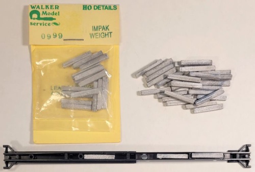
Below: Spine cars are inherently light weight, which compromises
their tracking reliability. So I installed Walker Model Service 0999 Impak
(sic) weights in the centersills. These are no longer available (I bought
mine many years ago). I cut some weights shorter to fit between the
various features inside the centersills. I also used small lead shot to fill
in smaller areas (sorry, no photos).
entire website copyright Gregg Fuhriman
created with CoffeeCup Visual Site Designer
created with CoffeeCup Visual Site Designer
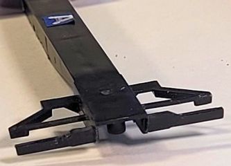
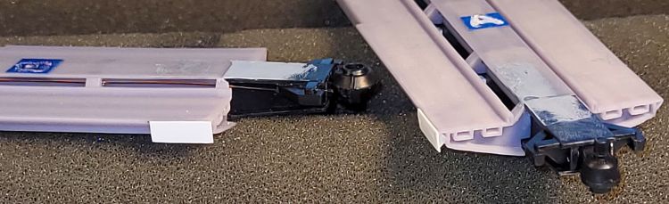
Below: I removed the four platform supports from the centersill bottom
flanges, since they interfered with the 3D-printed platforms. And I
glued in the stock Athearn "ball-and-cup" inter-unit couplings.
flanges, since they interfered with the 3D-printed platforms. And I
glued in the stock Athearn "ball-and-cup" inter-unit couplings.
Below: I used 0.060" square styrene strip to fill the brake gear mounting
slots on units that won't get the triple valve/reservoir combo part.
slots on units that won't get the triple valve/reservoir combo part.
Left and Below: I carefully cut out the molded
walkways, working around the brake stand
housing on the B unit.
walkways, working around the brake stand
housing on the B unit.
Below: I added small square styrene strip to
the walkway undersides. When the walkways
are glued to the car framing, they will be
raised up a little to replicate the prototype.
the walkway undersides. When the walkways
are glued to the car framing, they will be
raised up a little to replicate the prototype.
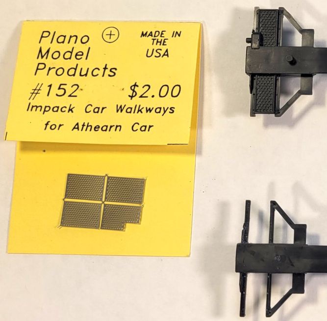
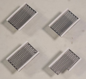
Below: I used Plano Models #152 etched metal see-through
walkways specifically designed for the Athearn Impack car.
I used 0.060" square styrene strip to fill the gaps in
the framing on the Athearn end ladders. These
subassemblies were then glued into the modified
end walkway frames.
Note: I installed the metal walkways after painting
the car white, since they should look like bare metal.
the framing on the Athearn end ladders. These
subassemblies were then glued into the modified
end walkway frames.
Note: I installed the metal walkways after painting
the car white, since they should look like bare metal.
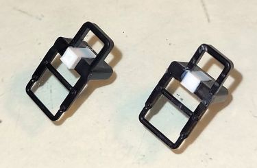
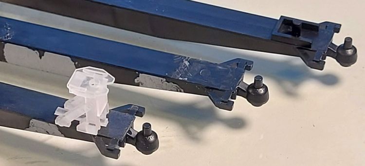
Right: Athearn "cheated" a little,
and molded big blocky hitch bases
on the mid-unit centersills so that
all 10 Athearn hitches could be
identical. Since I used correctly-
sized 3D printed hitches, where
the mid-unit hitches are taller than
the end unit hitches, I had to carve
off the Athearn bases.
At upper right is the stock base;
at center the base has been roughly removed; at lower left
the centersill has been sanded
smooth and a sample 3D printed
hitch placed for illustration.
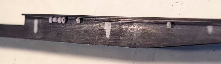
Right: "Phase 1" brake rigging
was done before I installed the 3D
printed platforms. I lightly scored a
line on the centersill sides 0.040"
down from the upper flange on
both sides of all units. I drilled
holes along the score line for the
3D printed pipe fittings to glue in.
Where ever possible, I used
prototype photos to locate the
various fittings on each unit.
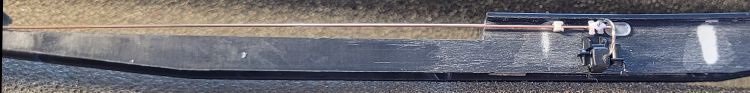
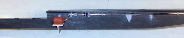
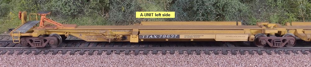
Right: The A unit right side has a
stock Athearn reduction valve. I
added a curved pipe tied into the
train-line which routes "through"
the oval false slot to the left side.
The phosphor bronze wire "pipe"
is placed temporarily for fit check.
In "phase 2" of brake-rigging, after
the platform is in place, the wire
will be threaded through the pipe
fittings and the platform's "D"
shaped cutouts, then fixed in place
with ACC.
Right: The G unit left side. I used
0.010" styrene to create mounting
brackets, such as this one for the
small reservoir (a modified brake
cylinder salvaged from my scrap
box). For pipe junctions, I placed
two "pipe support" fittings, drilled
a hole between them, and later
installed the branching "pipe" with
a third "pipe support" fitting (see
the A unit pics, just above).
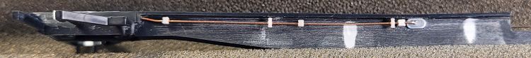
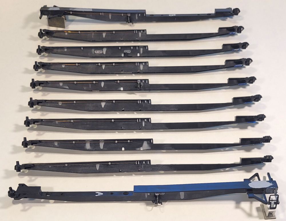
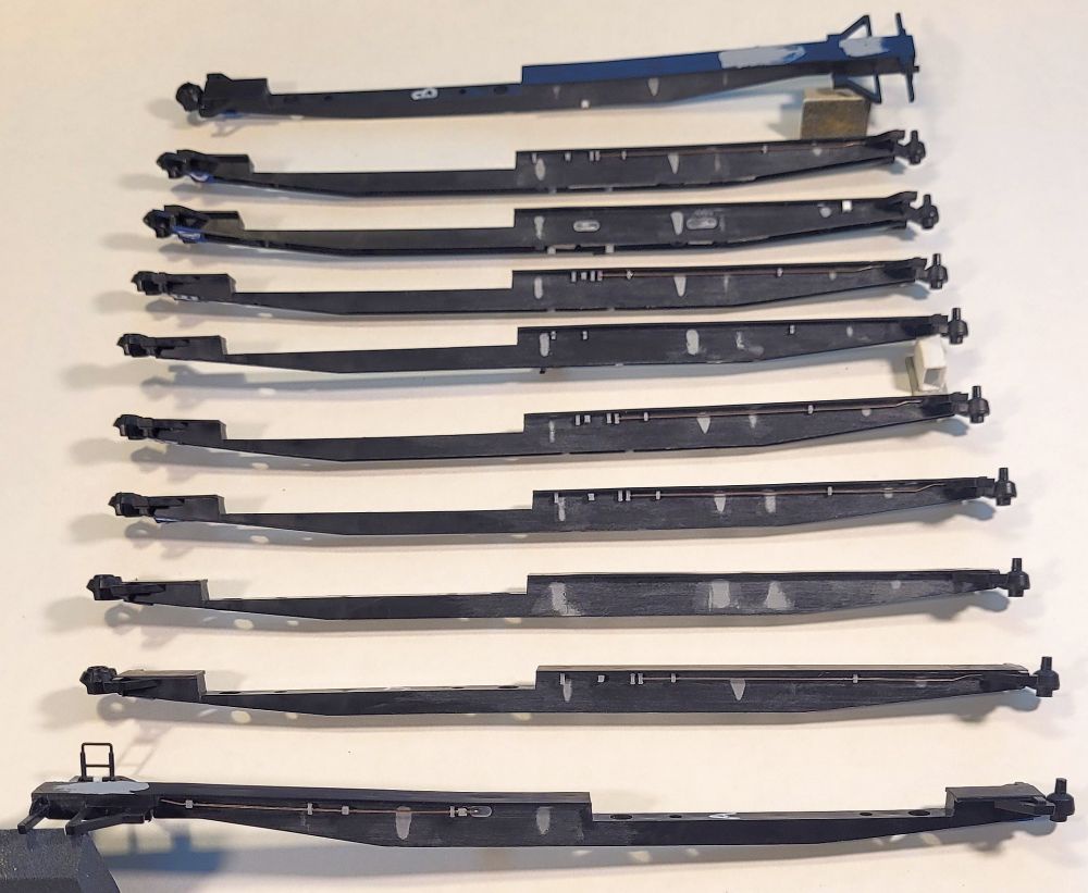
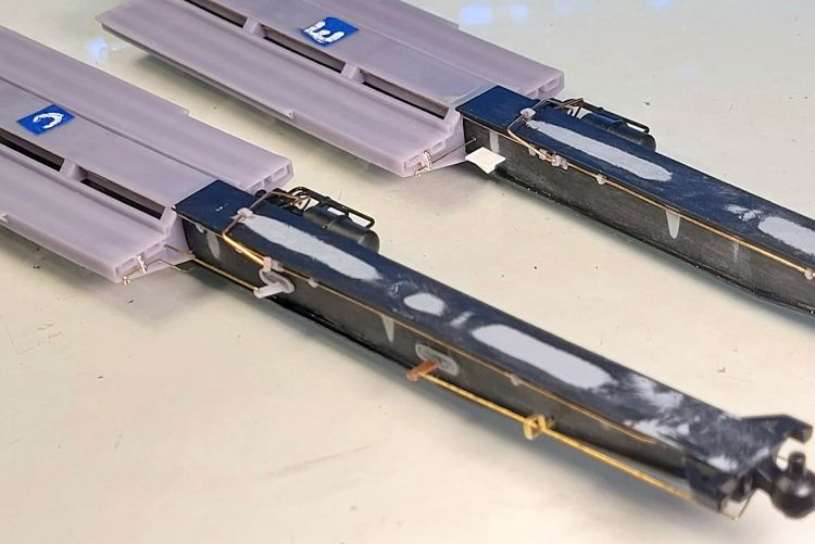
Below: All the units at the end of "phase 1" brake rigging. The 3D printed fittings and oval false slots are in place, as are the wire
"pipes" that do not need to thread through the platforms. The three reduction valves and their curved pipes are installed as well.
Not mentioned above: The Athearn centersills had noticeable molding "sinks", which I filled and smoothed with Tamiya gray
modeling putty before starting the brake rigging process.
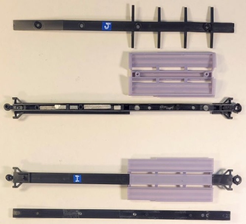
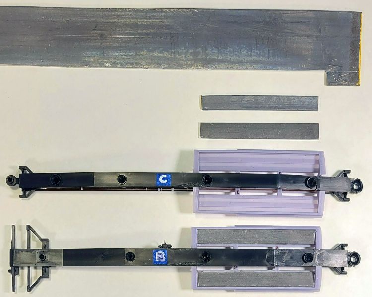
Below: Next I installed the 3D printed platforms into the Athearn centersills. To add weight, I used sheet lead
to make rectangles that fit into the undersides of the trailer platforms, attached with clear rubber cement.
I then installed the Athearn centersill bottom flanges. These have three screw holes with small lips around
them - after this photo, I sanded off those lips since they aren't prototypical (I didn't install screws in the holes).
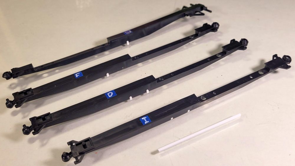
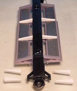
Below: I made replacement
platform supports from 0.040" styrene and ACC glued them
to the lead weights.
platform supports from 0.040" styrene and ACC glued them
to the lead weights.
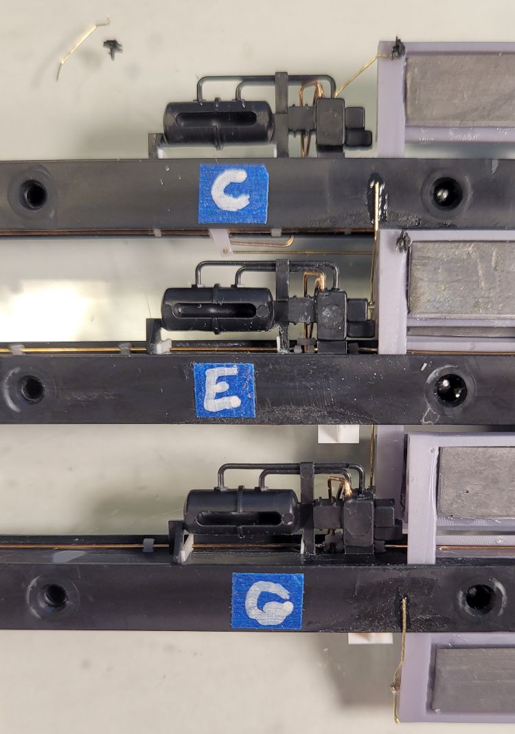
Note how I temporarily marked
each unit with its letter, just to keep things straight during the build!
each unit with its letter, just to keep things straight during the build!
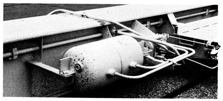
Right: I almost wore out this image
staring at it during this build. It
reveals how all the piping comes
together at each of the five triple-
valve/reservoir combos, how the
mounting brackets are placed,
the over-the-centersill piping, and
the retainer equipment setup.
There is also a short, angled
U-shaped pipe from a junction
in the train-line to the triple valve.
Gordon Odegard photo, from the
Sept. 1982 Model Railroader that
has scale drawings of a 10-pack.
Right: To get a more delicate look,
I modified the stock Athearn triple-
valve/reservoir parts by removing
material along the mounting edge.
Left is stock, right is modified.
I also drilled holes in the triple valve
to accept wire "pipes" (not shown).
Note that I did not mess with the
two "pipes" connecting between
the reservoir and the triple valve.
They looked good enough for me
as-is and I figured I wouldn't be
able to improve on this.
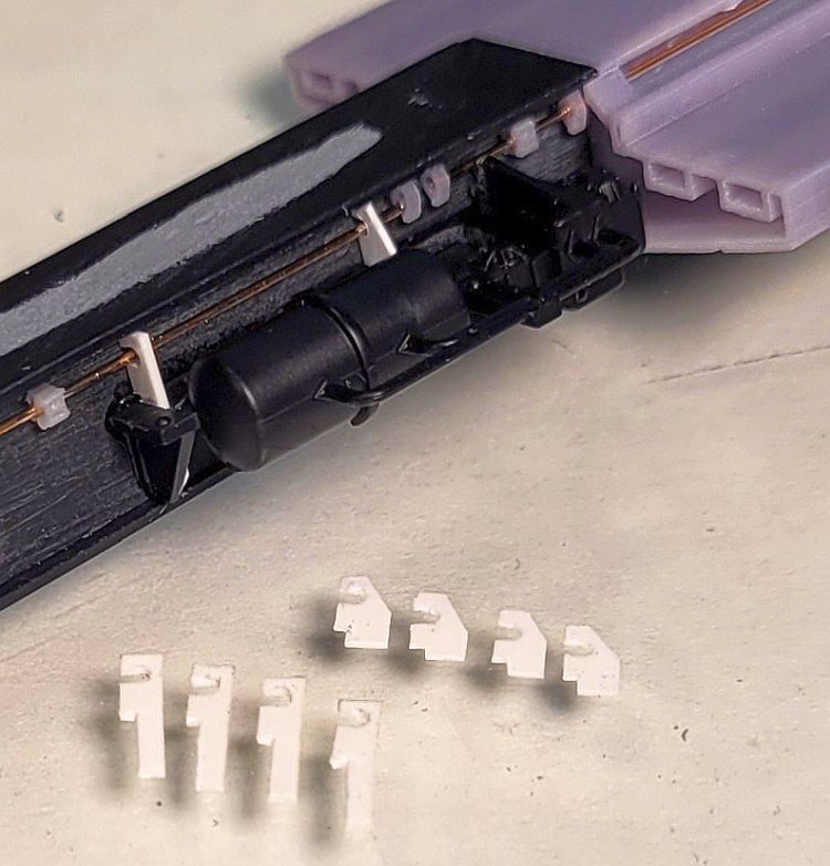
Right: I installed the wire "pipes"
running through the platforms and
my pre-installed 3D fittings on
all units.
For units C, E, G, H, and J, I then
glued in the modified triple-
valve/reservoirs.
running through the platforms and
my pre-installed 3D fittings on
all units.
For units C, E, G, H, and J, I then
glued in the modified triple-
valve/reservoirs.
Right: I made additional mounting
brackets from 0.010" styrene and
glued them on either end of the
reservoirs.
brackets from 0.010" styrene and
glued them on either end of the
reservoirs.
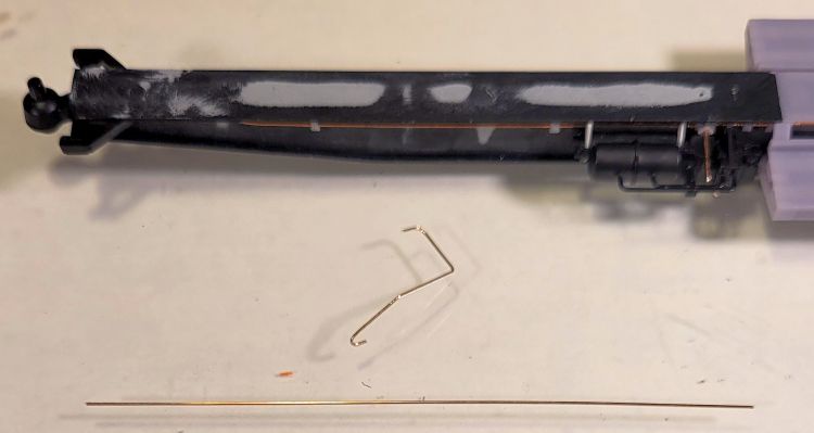
Right: I first added the short
U-shaped pipe from the train-line
to the triple valve.
Next I formed the complex over-
the-centersill piping from brass
wire. After drilling a hole in the top
of the centersill for the 3D printed
"pipe support" fitting, I threaded
the fitting onto the wire, fit it in
place, and then fit the wire ends
into their pre-drilled holes on the
triple valve and the centersill on
the opposite side.
Needless to say, this was a very
fiddly process!
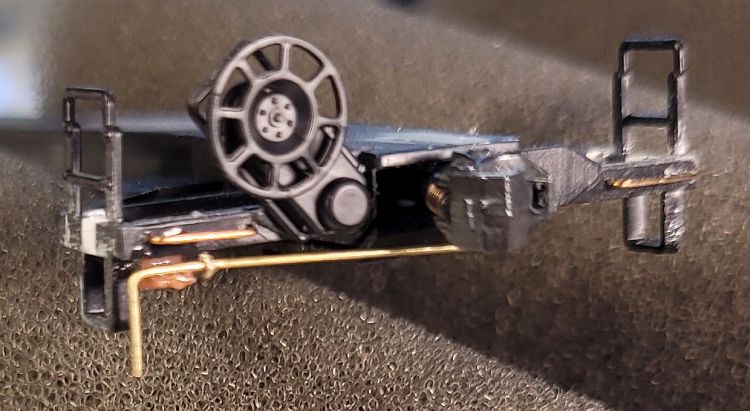
Right: The finished over-the-
centersill piping sits at an angle
to the centersill.
This view also shows the two
variations of retainer handles,
formed from 0.008" wire. I made
small mounting brackets from
0.005" styrene, which are glued
to wire lift rings glued into holes
drilled into the platform ends.
On the E unit, note the "derelict"
mounting bracket made from
0.010" styrene.
On the C unit, I made brake rods
from brass wire and connected
them to the brake levers at the
oval false slots. One 3D-printed
lever broke off its slot, so I
replaced it with a plastic part.
I made square-profile rod support loops on units B, C, and D by
shaping flat brass wire, and filing
the mounting end into a peg shape
for gluing into a hole drilled in the
centersill.
Right: I mounted Precision Scale
31797 retainer valves on the
platform bottom edges, and
added 0.008" wire "conduits"
from them to the triple valves.
This bottom-side view also shows
how the wire "pipes" and the
retainer conduits fit into the triple
valves, and the placement of the
styrene brackets I added.
As a simplification, the retainer
handles passing beneath the
centersills are glued to the
centersill bottom flanges,
and do not actually connect
to the triple valves.
Right: I used 0.010" styrene to
make the plates mounted to the
platform edge on the A unit left
side and B unit right side. Two
tiny trapezoid-shaped support
brackets are fitted between the
plate and the platform edge.
These plates carry the lube data
and "Ft-93" class markings.
make the plates mounted to the
platform edge on the A unit left
side and B unit right side. Two
tiny trapezoid-shaped support
brackets are fitted between the
plate and the platform edge.
These plates carry the lube data
and "Ft-93" class markings.
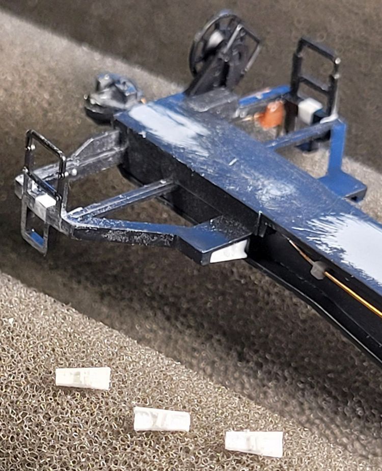
Right: On both end units A and B,
I installed straight wire grabs and
a cut lever bracket. For strength, I
mounted a wire lift ring and passed
a wire cut lever through it, which
is also glued to the bracket. The
levers are not actually attached
to the Kadee couplers.
On the the B unit, I installed
the stock Athearn angled brake
housing and wheel.
After painting and weathering, I
also added Hi-Tech Details
rubber train-line air hoses at
both ends.
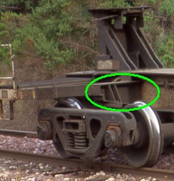
Right: Late in the game I noticed
the prototype (below) has some
visible structural shapes filling out
the bolster. I made some stand-in
parts from styrene angle with two
small vertical stiffeners, and tucked
these into the Athearn bolsters.
the prototype (below) has some
visible structural shapes filling out
the bolster. I made some stand-in
parts from styrene angle with two
small vertical stiffeners, and tucked
these into the Athearn bolsters.
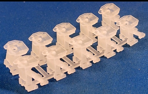
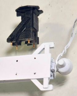
Right: I bought a set of 3D-printed
10-pack hitches from Shapeways.
These are more accurate than the
Athearn hitches in that the set has
two slightly shorter hitches for the
end units. Those hitches are
shorter to compensate for the
slight upslopes of the end unit
centersills. These are no longer
available, unfortunately.
Far right: For added strength, I
drilled holes in the hitch bottoms
and the centersill tops, and used
small bits of wire for mounting
pegs. I ACC glued on the hitches
after painting.
Not shown: To get smoother
centersill tops, I used Tamiya
gray modeling putty to fill and
smooth molding "sinks" in
the tops of the Athearn
centersills, and the joints
where the 3D platforms mate
with the Athearn centersills.
centersill tops, I used Tamiya
gray modeling putty to fill and
smooth molding "sinks" in
the tops of the Athearn
centersills, and the joints
where the 3D platforms mate
with the Athearn centersills.
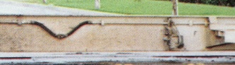
Below: A prototype flexible joint on unit F, right side.
These were also on units E and I, added by Santa Fe during the brake system modifications.
These were also on units E and I, added by Santa Fe during the brake system modifications.
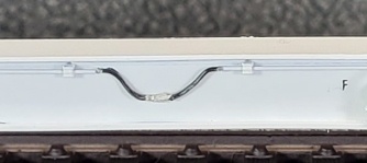
Below: A finished joint on my model unit F,
installed after painting and decals.
installed after painting and decals.
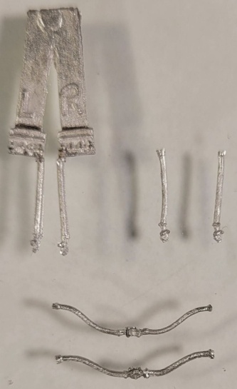
Right: I made the flexible joints from Details West cast
metal diesel MU hoses. After cutting two hoses from
the sprue, I formed them into the characteristic "droopy"
shape, then ACC glued their couplings together.
metal diesel MU hoses. After cutting two hoses from
the sprue, I formed them into the characteristic "droopy"
shape, then ACC glued their couplings together.